4-1 单周期数据通路
Datapath Elements
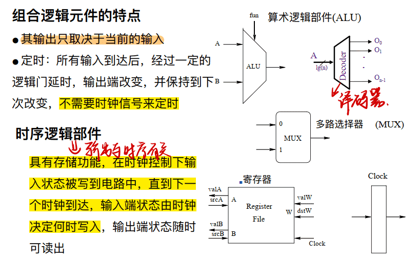
- 计算部件:组合电路输出随输⼊变化, ⽐如 ALU (+ - × ÷)
- 状态部件(必须有时钟)
- 时序逻辑电路
- 输出随时钟边沿变化
- ⽐如寄存器 Register
组合电路和时序电路区别:
- 组合电路:输出只与输入有关
- 时序电路:输出与时钟有关
单周期CUP
-
单周期(Single-Cycle) CPU执⾏⼀条指令⽤⼀个时钟周期 (一周期完成一条指令)
-
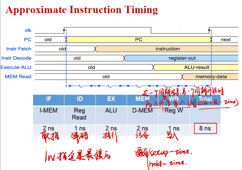
==在时钟上升沿保存指令的结果和下⼀条指令的地址==
-
Data path 上的资源每指令周期最多⽤⼀次 (一周期中每个部件/指令只能用一次)
时序逻辑电路 State (sequential) elements
- 定时⽅式:规定信号何时写⼊状态元件或何时从状态元件读出
- 边沿触发(edge-triggered)⽅式:状态单元中的值只在时钟边沿改变。 每个时钟周期改变⼀次
- 最简单的状态单元
- D触发器: ⼀个时钟输⼊、 ⼀个状态输⼊、 ⼀个状态输出
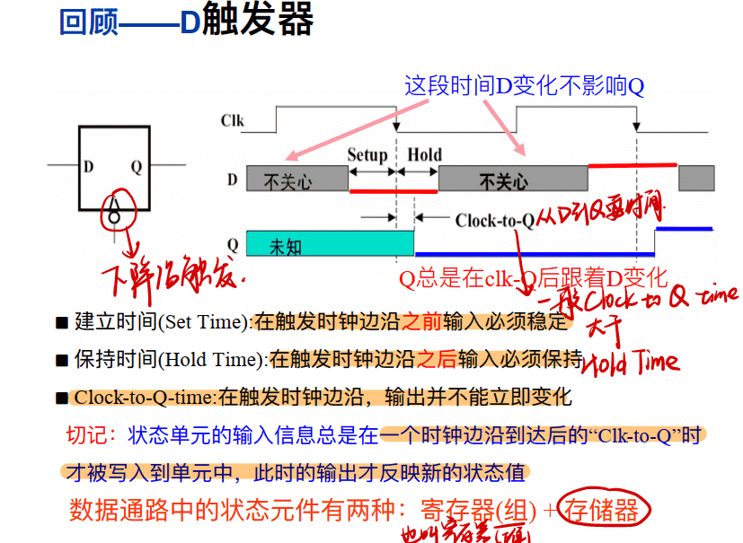
Clock-to-Q-time:即从输入到输出的时间
存储单元
- 寄存器
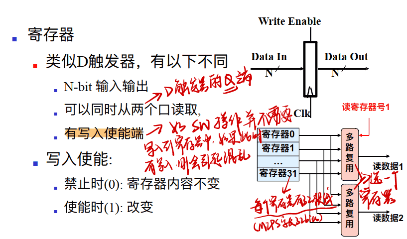
- 寄存器组
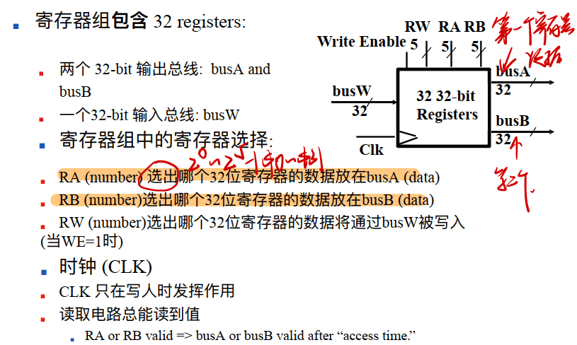
寄存器组内部:
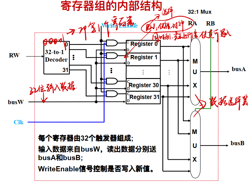
-
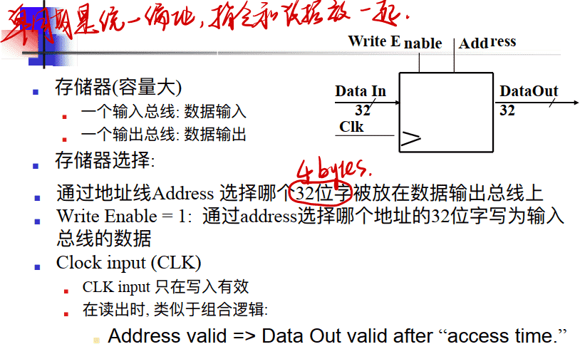
存储器(内存)
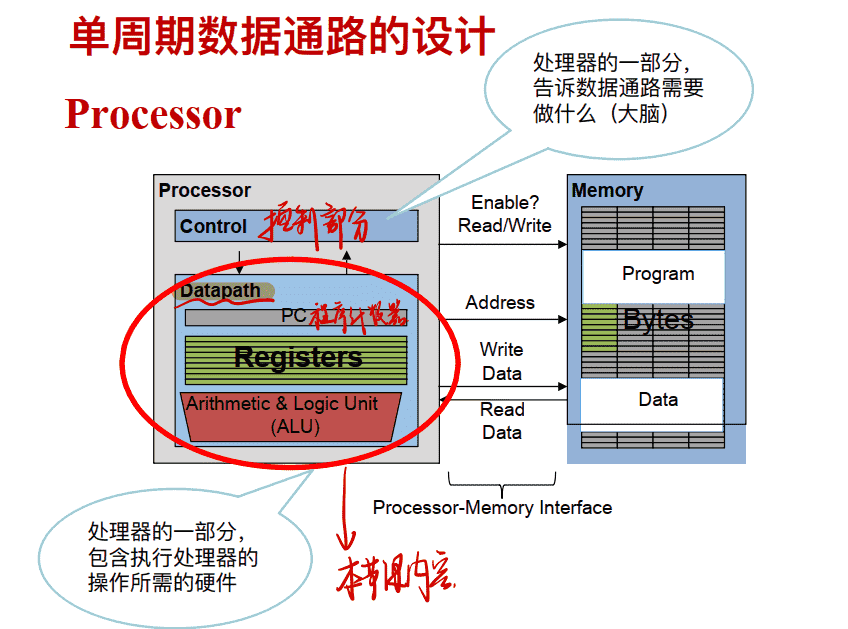
单周期数据通路设计
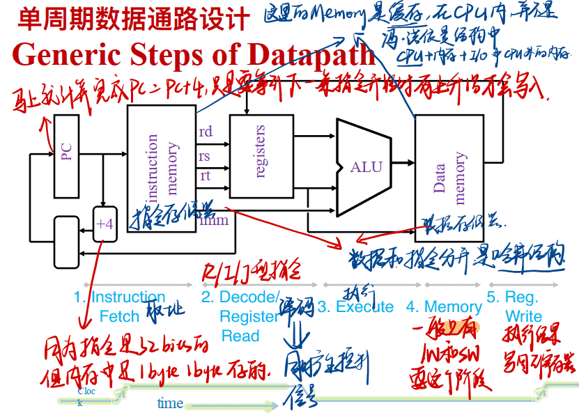
Memory只有lw和sw的指令需要这个阶段
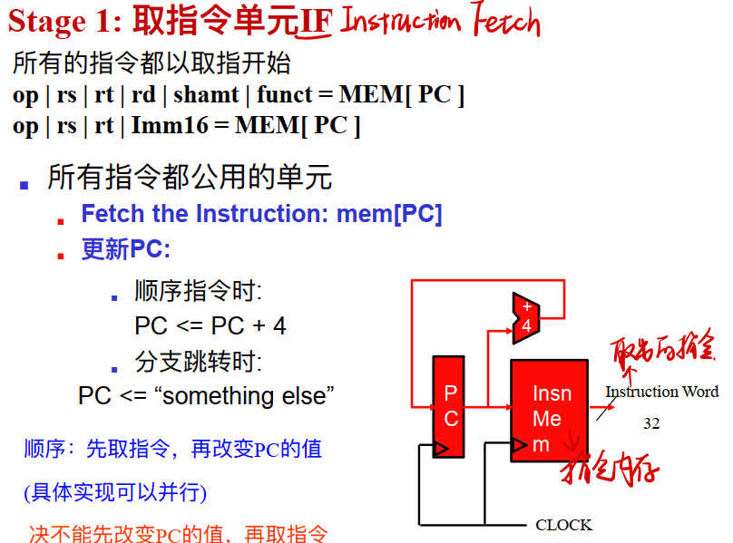
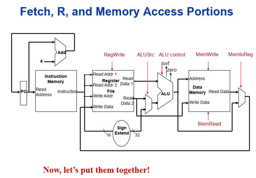
Stage 1: 取指令单元IF (Instruction Fetch)
Stage 2: 指令译码Instruction Decode
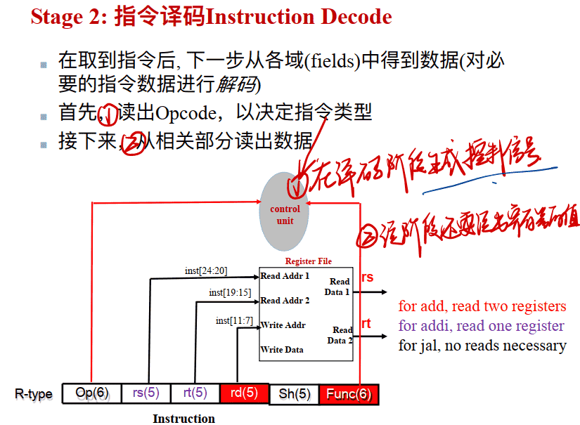
在译码阶段生成控制信号
请注意, 在译码阶段, 使⽤ rs 和 rt 指令的字段地址从寄存器堆的读取端⼝读出寄存器内容, 对所有指令都是⼯作的
- 因为还没有译码, 所以还不知道指令要做什么 !
- 提前读出两个源操作数内容, 以防后⾯⽤到两个寄存器的内容。
- ⼏乎所有指令都会⽤到寄存器内容 (除了 j 指令)
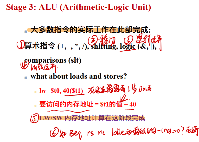
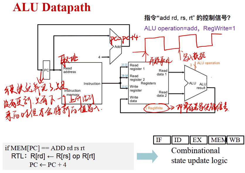
Stage 3: ALU (Arithmetic-Logic Unit)
Stage 4: 内存访问Memory Access
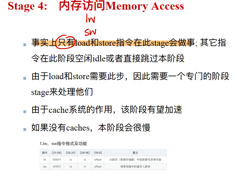
这里的内存是在CPU内的caches,是高速内存(缓存),里面的内容是外部内存的复制,而不是冯诺依曼结构中的CPU、内存、I/P中的CPU外部的低速内存
Stage 5: 写寄存器Register Write
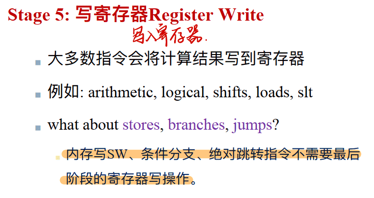
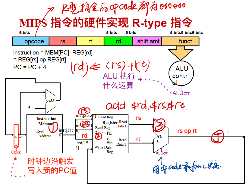
MIPS指令的硬件实现
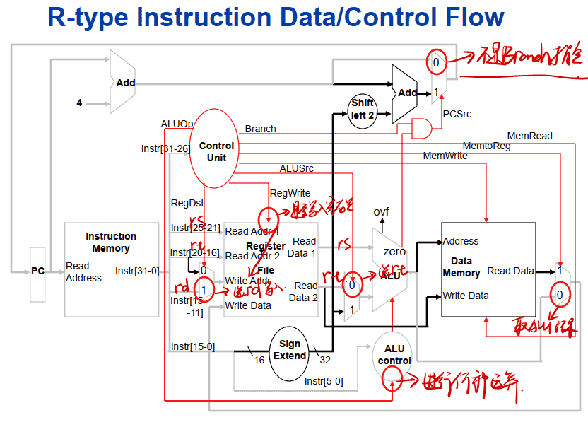
R-type 指令
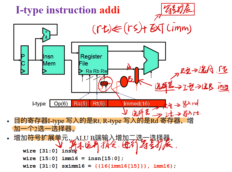
I-type instruction addi
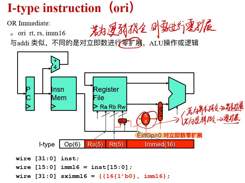
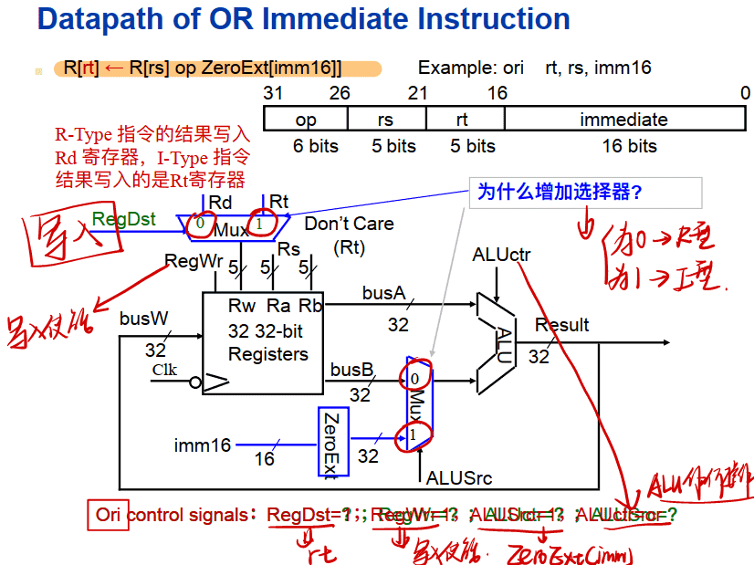
I-type instruction ori
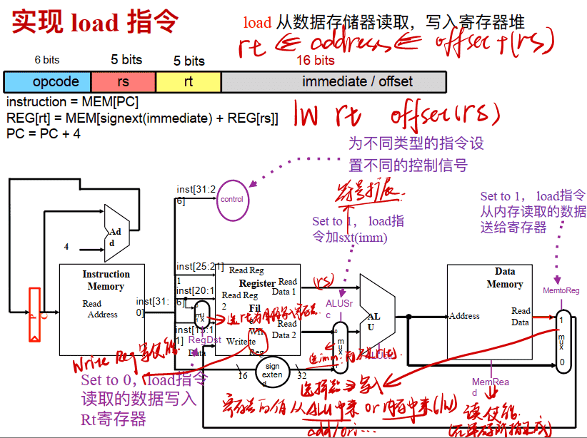
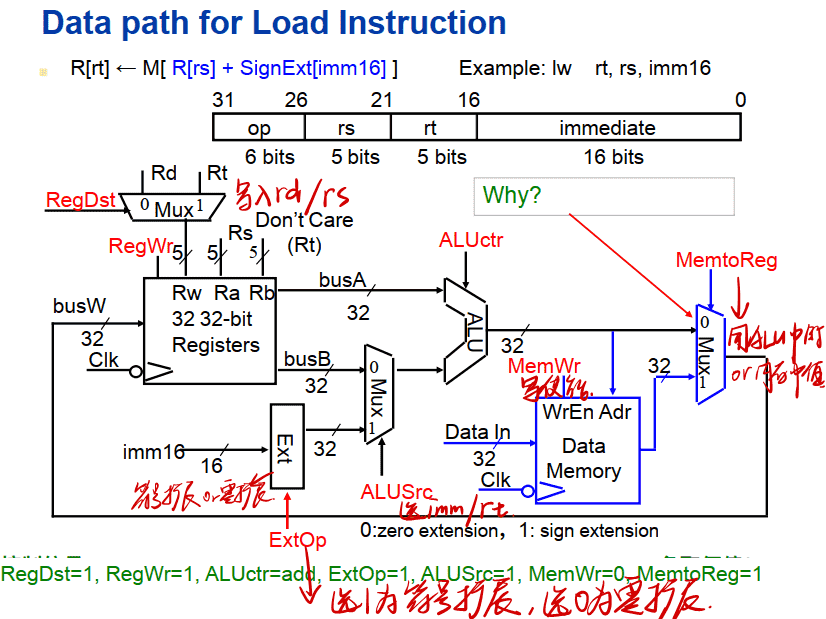
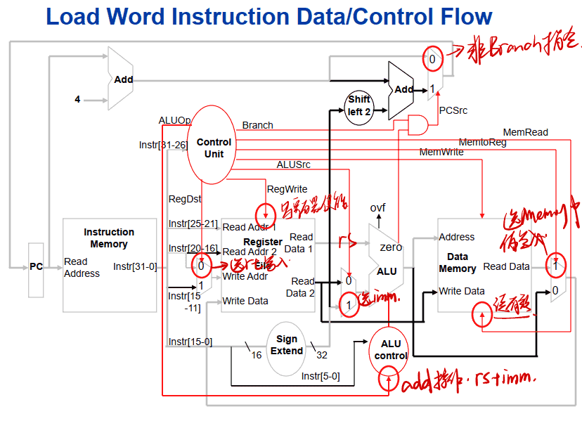
实现 load 指令
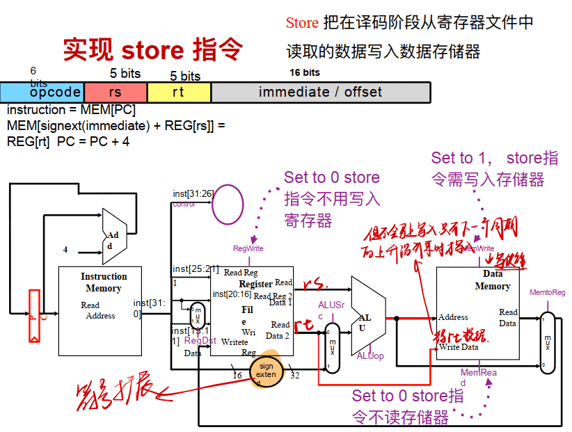
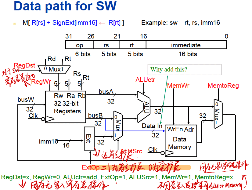
实现 store 指令
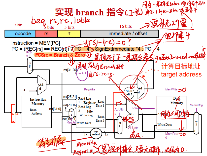
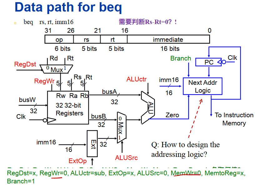
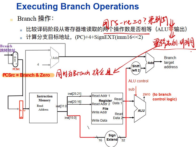
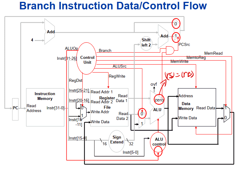
实现 branch 指令
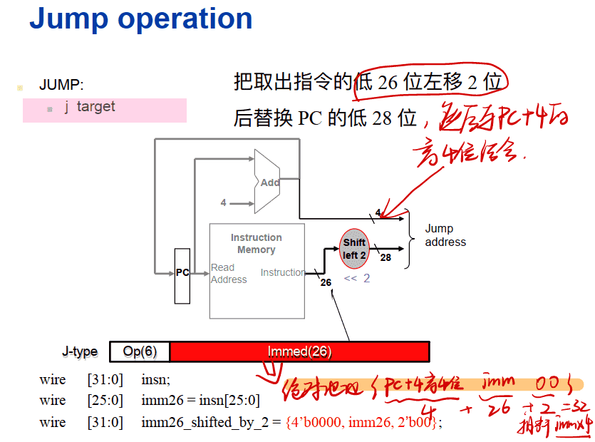
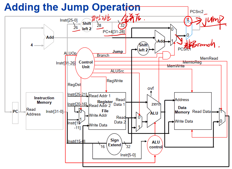
Jump operation
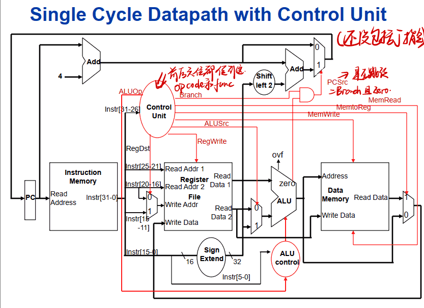
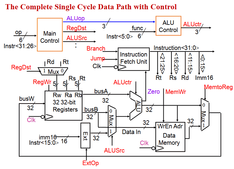
# Single Cycle Datapath with Control Unit
R-type Instruction Data/Control Flow
Load Word Instruction Data/Control Flow
Branch Instruction Data/Control Flow
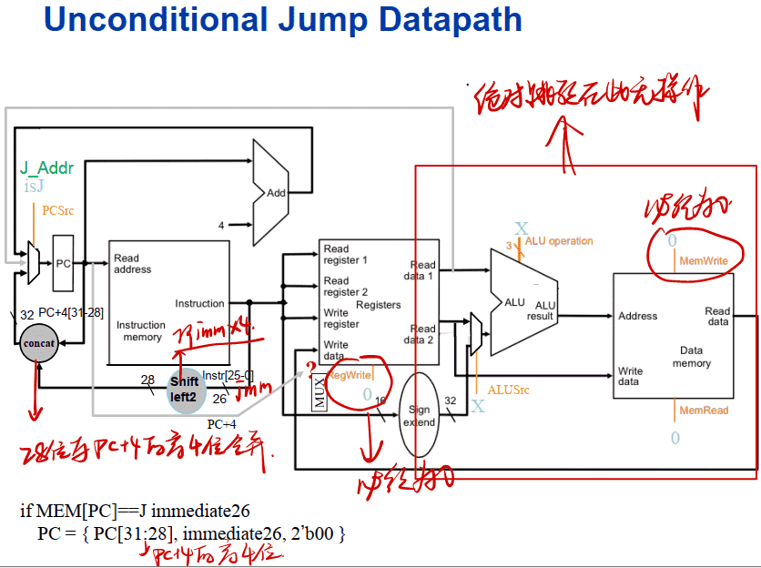
Adding the Jump Operation
MIPS R2000 instruction set 扩展内容
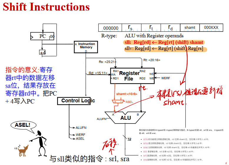
Shift Instructions
-
J/JAL
-
JR/JRAL
-
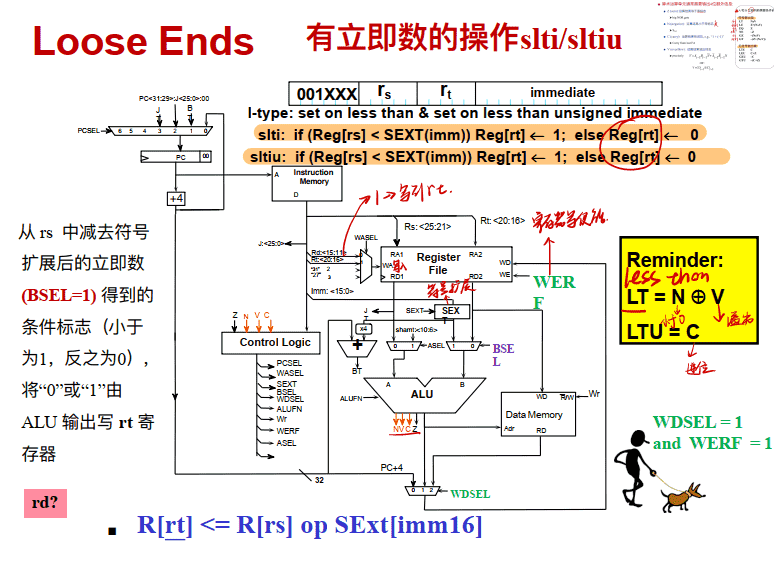
slti/sltiu
-
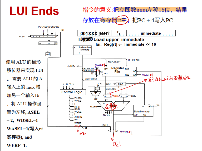
LUI
-
Reset(复位), Interrupts(中断), and Exceptions(异常)
Q:前⾯的设计没有包括 JR, JAL, JALR, Shift ,slti/sltiu …这些指令?
A:添加选择器和对应功能
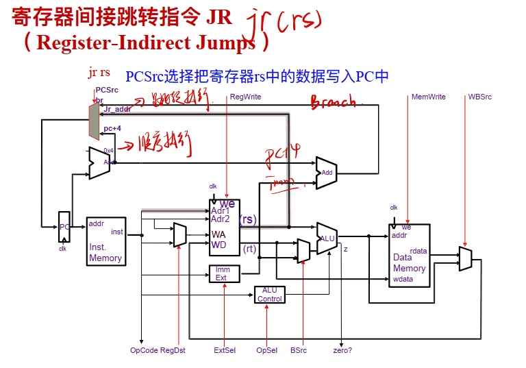
寄存器间接跳转指令 JR( Register-Indirect Jumps )
Register-Indirect Jump-&-Link (JALR)
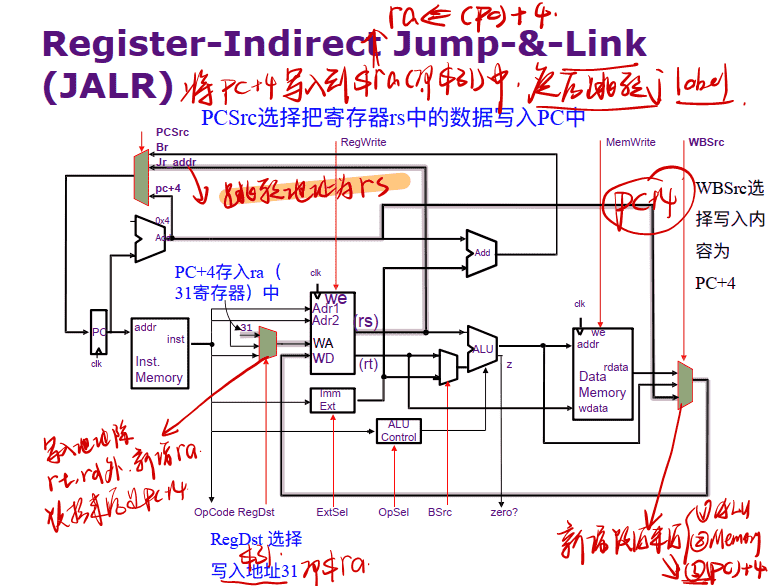
==jalr跳转地址为rs,jal跳转地址要用26位imm==
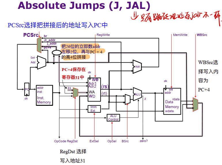
Absolute Jumps (J, JAL)
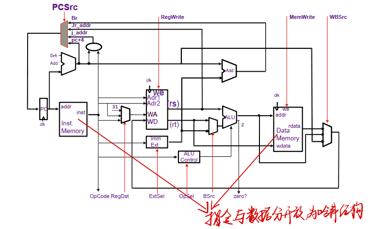
Harvard-Style Datapath forMIPS
Shift Instructions
有立即数的操作slti/sltiu
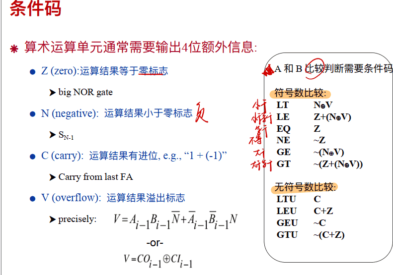
回顾:3-1中条件码
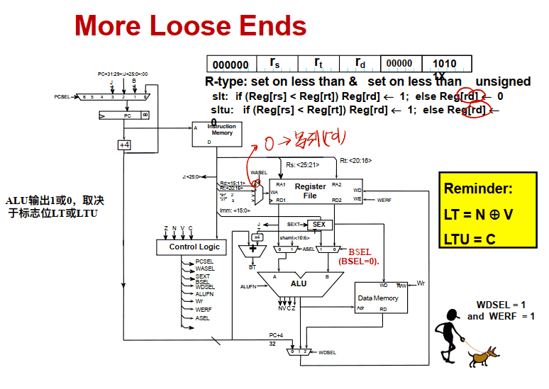
slt和sltu(两个寄存器比较,无立即数)
LUI
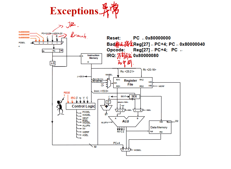
Reset, Interrupts, and Exceptions
Exceptions
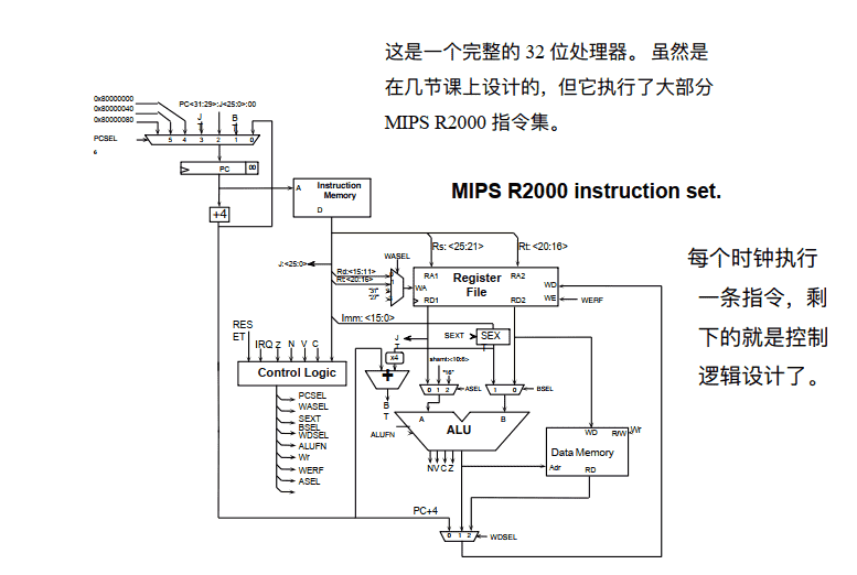
完整的MIPS M2000
单周期控制器的设计 Control
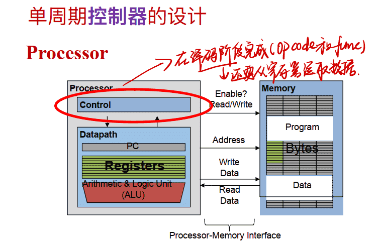
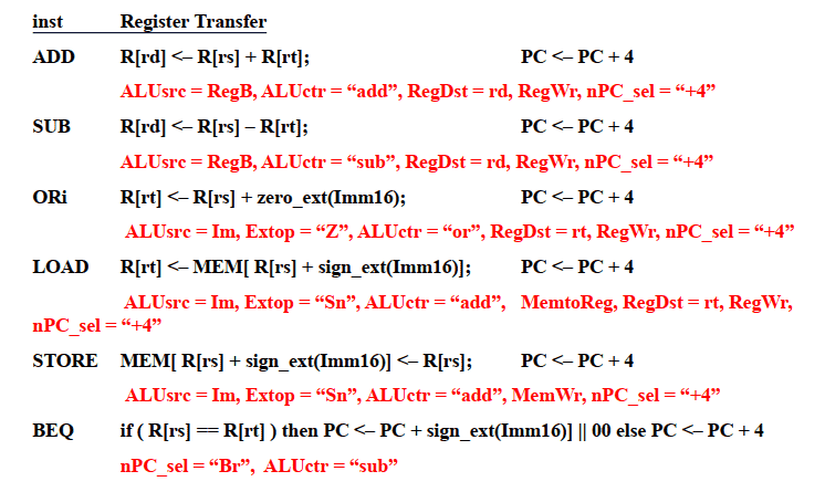
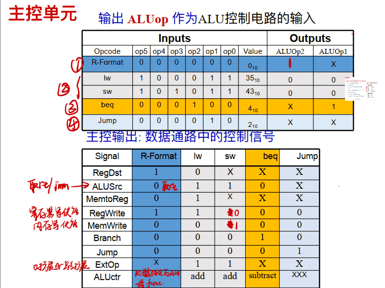
Recap: A Summary of Control Signals
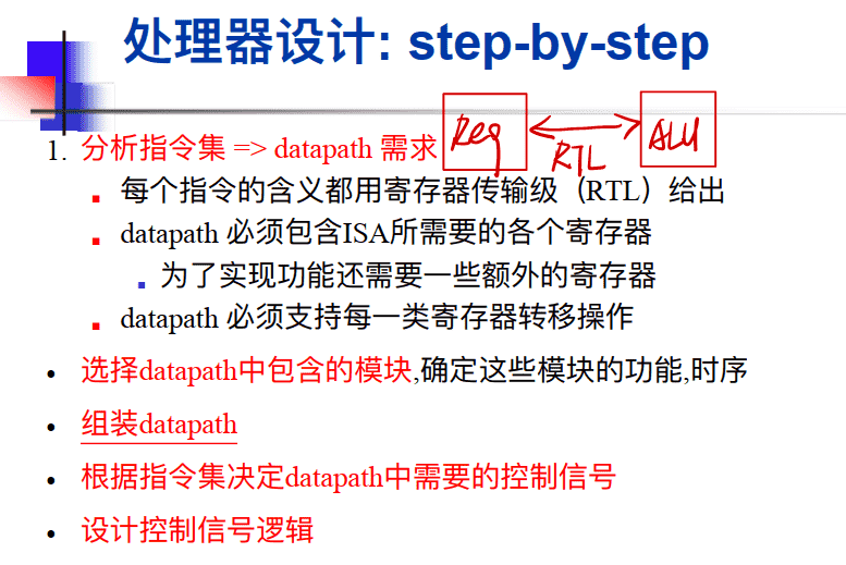
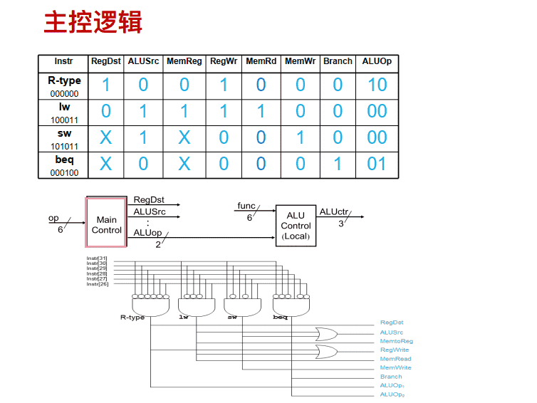
控制器的设计
-
实现⽅式: 组合逻辑电路 输⼊信号: • 指令字段的op和func。 • ALU的zero、 V、 N状态
- 确定每条指令的控制信号
- 0
- 1
- X(与该指令⽆关)
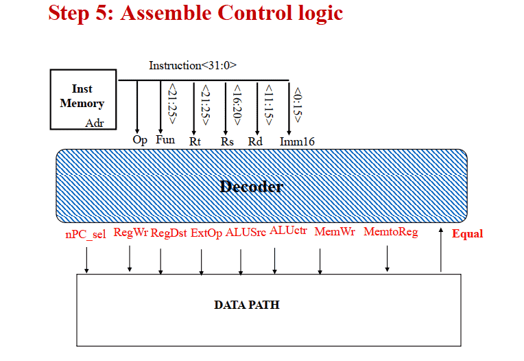
- 构建控制信号的真值表
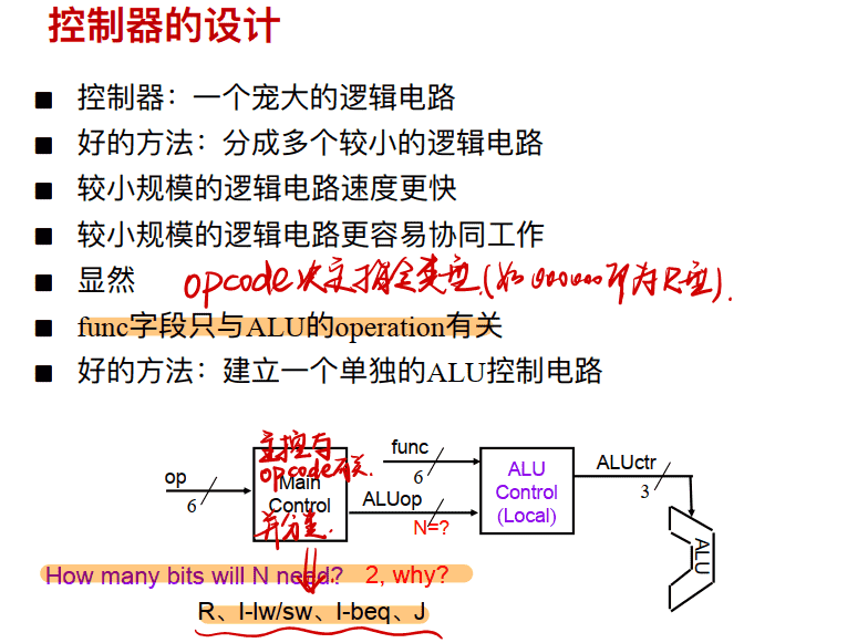
分为主控和ALU控制
主控单元
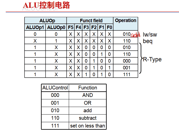
ALU控制电路
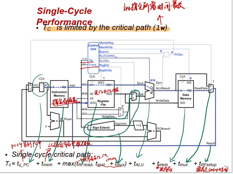
The Complete Single Cycle Data Path with Control
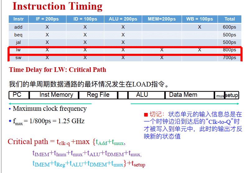
时钟频率
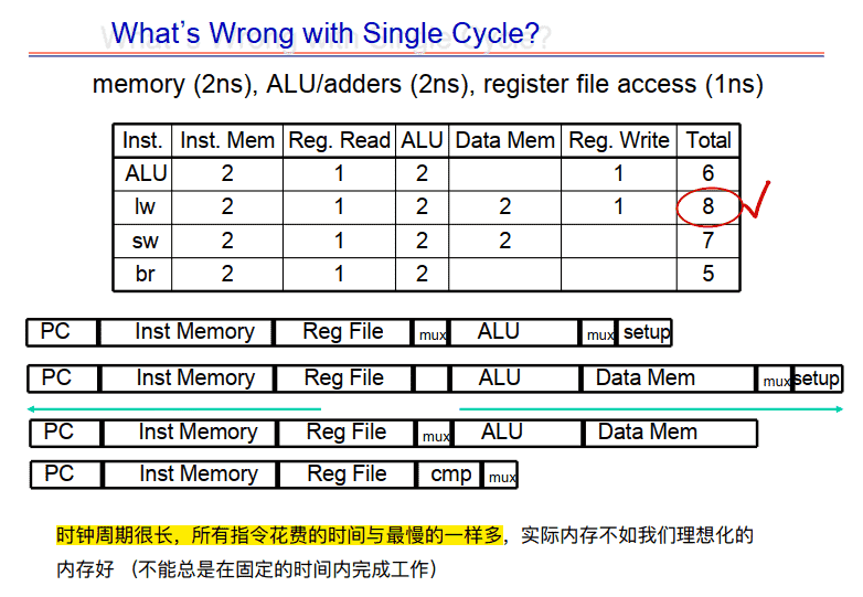
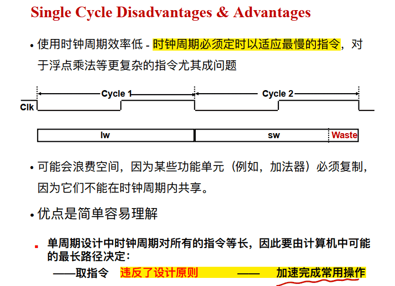
Single Cycle Disadvantages & Advantages
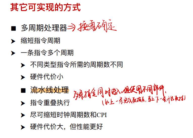
其它可实现的⽅式
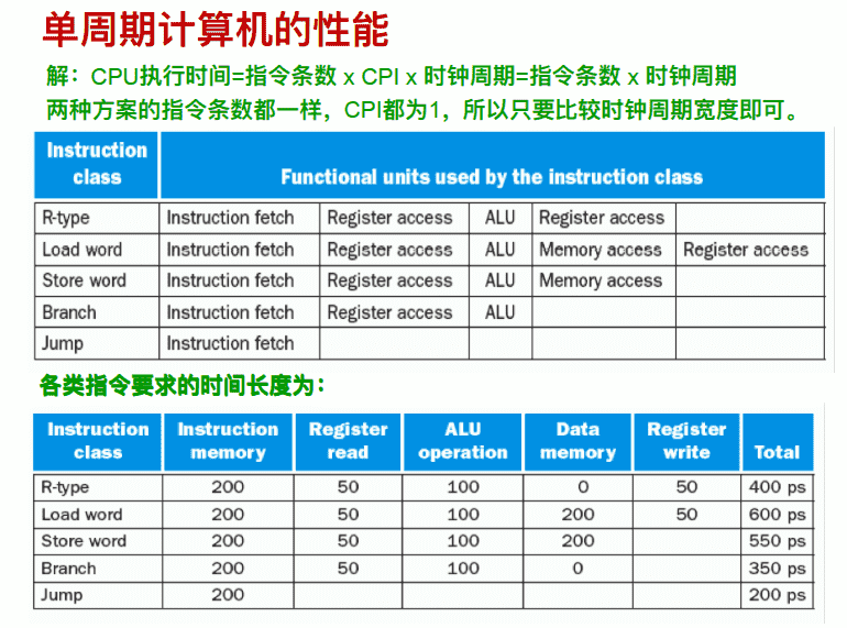
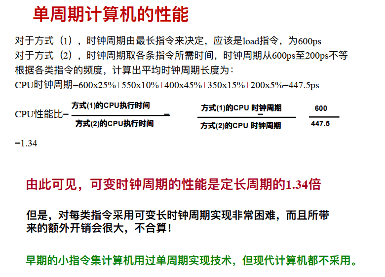
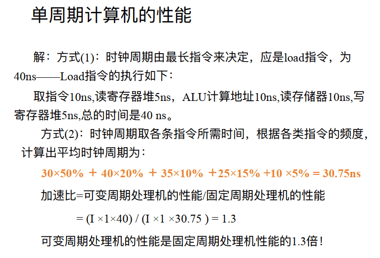
单周期计算机的性能